
Technical code practice
…using sustainable design
To address this, temporary Technical code practice are sometimes required. These serve only as interim guidelines until official regulations are clarified or updated. Below are a list of possible such practices according to Eurocode.
Most proposed assumptions originate from former designers at VBk.
1. Requirements service state frequent (SLS-F) prestressed bridge
SS-EN 1992-1-1 Table 7.1N specifies “absence of tensile stresses” for SLS-F.
It is not clear whether this refers to “absence of flexural tensile stresses” or “absence of principal tensile stresses.” Generally the former interpretation is used, thus no check of principal tensile stress is performed.
Without any requirements of permissible principle tensile stress , a prestessed bridge risks cracking in service state, thus behaving as a RC bridge. This was not generally considered desirable historically.
Historically principle tensile stress may not exceeed 0.66 fctk,0.05 at level of prestress.
To avoid risk mentioned above, the use of SS-EN 1992-2, section 7.3.1 (110) is recommended. Here is stated that in certain cases where shear and torsion may cause cracking, Annex QQ should be applied. Permissible principal stress is derived on assumption compressive stress is less than 0.60 fck.
With this assumption permissible principal tensile stress may not exceed 0.52 fctk,0.05 in entire web, in principle entire cross section.
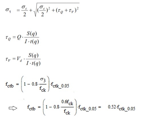
If principle compressive strengh 0.60 fck is assumed according to Annex QQ it gives lower permissible principal tensional stress than historically. If principle compressive 0.43 fck is assumed then permissible tensile stength is 0.66 fctk,0.05, thus same as historically.
2. FEM modelling of frame bridges: edge beams and wingwalls
Frame bridges are historically considered to be “walls” or “slabs”. To achieve this edge beams and wingwalls are considered static inactive in the longitudinal direction of structural system.
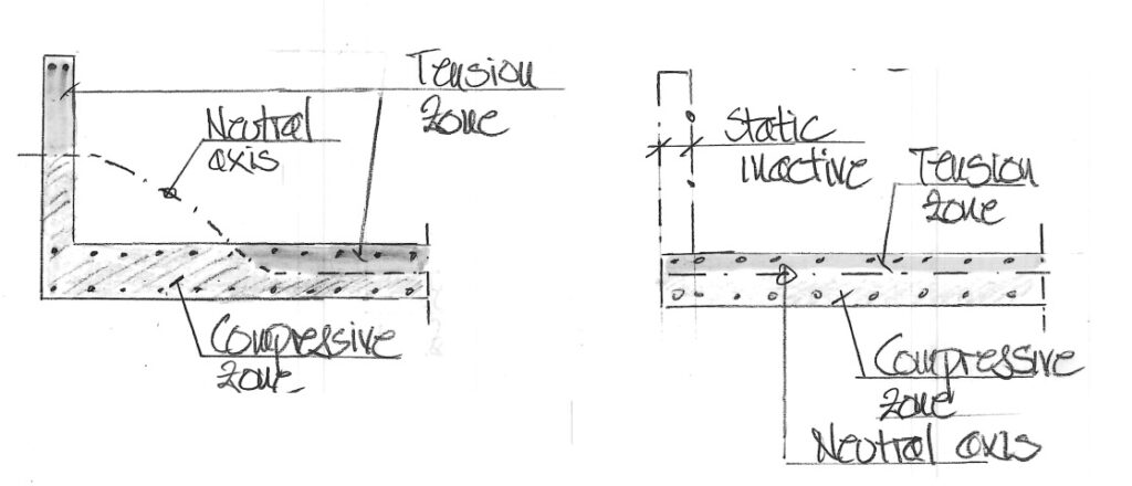
This assumption permits future replacement or removal without affecting the longitudinal structural system.
This assumption is based on assumed cracking and using nominal reinforcement to reduce size of cracks in the vertical direction.
Historically, high edge beams (typically in railway bridges) have been provided with vertical slits.
3. Angular stiffness for slab foundation
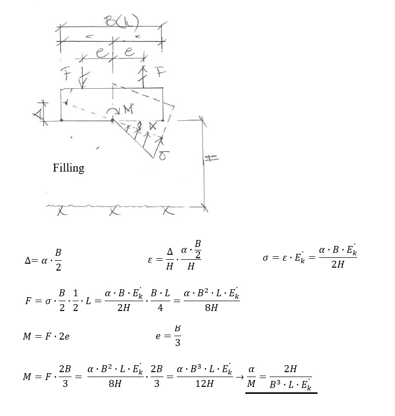
When distance to rock is greater than 2B there is a solution provided. When this condition is not fullfilled the situation somewhat amgigous. The derived solution below is suggested.
The equivalent E-moduls for soil is termed E´k and can be derived in several ways but a method using load distribution 2:1 is recommended, see menu “Code check” program G3.002.
Auto
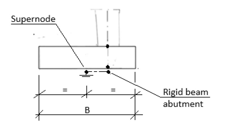
When bottom slab is constructed with abutment positioned not at center of bottom slab, introduce rigid link as seen below.
4. Vertical stiffness for slab foundation
If only one support on a single foundation, vertical stiffnes should be modelled as rigid.
If several supports act on a single fundation (example closed frame bridge), a none rigid vertical stiffness must be used. See derivation below.
Vertical stiffness can be determined from settlements under loading.
When calculating settlements in the subsoil, a 2:1 load distribution method is applied.
If the obtained geotechnical modulus (Ek) of the soil is given as valid for 10 years, this must be taken into account when determining the vertical stiffness.
The effect of creep is calibrated using the formula:
α(t) = 1 + 0.2log(10t)
For a 10-year load duration → α(10 years) = 1.40
For short-term loads, use t = 0.1 years → α(0.1 years) = 1.00
For long-term loads, use t = 120 years → α(120years) = 1.62
Load:
q = 100 kPa
Stress distribution with depth:
σ(z) = q · (B + L) / ((B + z) · (L + z))
Settlement:
sₖ = ∫ σ(z) / Eₖ(z) · dz
Vertical stiffness:
Bₖ = q / sₖ
Vertical stiffness for short-term loads (variable loads; t = 0.1 years applied):
Bₖ(0.1 year) = (1.40 / 1.00) · Bₖ = 1.40 Bₖ
Vertical stiffness for long-term loads (permanent loads; t = 120 years applied):
Bₖ(120 years) = (1.40 / 1.62) · Bₖ = 0.86 Bₖ
5. Horizontal stiffness for slab foundation
Horizontal stiffness should be modelled fixed.
6. Difference in stiffness between RC and prestressed structural members
The difference in stiffness between RC and prestressed structural members should be considered in the FEM analysis of statically indeterminate prestressed concrete structures. According to established engineering practice, the stiffness of conventionally reinforced elements is taken as 60% of that of corresponding prestressed elements. This assumption is consistent with older code.
7. Torsional stiffness concrete structure
When distributing torsion in 3D FEM modell, the torsional stiffness 0.3Gc×Kv should be applied.
When determining Gc it is accepted that the poisson value (v) zero is applied, corresponding to cracked concrete, resulting in Gc = 0.5Ec.
8. Distribution width of load effects in slab structures
According to established historical design practice, internal forces are distributed over a distance of 3h. This assumption is considered statically sound due to very long tradition.
Distribution is in accordance with the FEM recommendations but modified such that “or” is applied instead of “min”, see equation below.
bef = (3h or L/10)
9. Permissible resistance shear reinforcement
When shear (Q) and torsion (T) act simultaneously, verification shall be carried out in the service state (SLS).
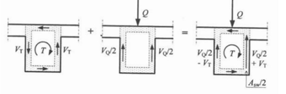
For slab bridges, the effect of torsion is generally negligible. Consequently, no reduction of the design yield strength (fwd) of shear reinforcement is required.
For beam bridges, both shear and torsion are typically present. The applicable code for verification of service state (SLS) is presently somewhat limited.
In cases when service state (SLS) verification is not performed, the design yield strength (fwd) of shear reinforcement is limited to 300 MPa. This assumption has traditionally been applied to RC beam bridges.
If a verification in frequent service state (SLS-F) demonstrates that the entire cross section remains uncracked, no reduction of design yield strength (fwd) is required. This is generally fullfilled in prestessed beams.
10. Reinforcement anchorage zone of prestressing cables
Shortly, a suggested method will be provided.
11. Geotechnical capacity shallow foundations
Determination of geotechnical bearing capacity using the “general bearing capacity equation” generally results in uneccessary safety. This since method originally was not intended for high horizontal forces (H > 0.2V) or located near a slope.
To increase geotechnical capacity using “circular cylindrical slip surface analysis” is useful. This method yields significantly higher geotechnical capacity.
The developement of advanced FEM software often yields even higher geotechnical resistance since can identify “failure surfaces that are non-circular”.
Increased geotechnical capacity can be achieved by not only considering the driving loads acting above level of foundation, but also by using resisting forces along failure surface above level of foundation.
Increased geotechnical capacity can be achieved including substructure in the calculation model. This can be done, for example, by assigning material properties with high internal friction, or geometrically constraining possible failure surfaces.
Menu “Assumption FEM analysis” report G2_2D gives an examples of the above suggestions.
12. Load capacity piles
The load capacity can be increased by performing an advanced FEM analysis in which second order effect of axial force due to lateral deflection including initial imperfection and variations in lateral soil resistance along the pile.
See section menu ”Assumptions FEM analysis” report G1_2D.
For bridge foundations there are additional ways of increasing load capacity, this since load effects typically vary in piles within a pile group. When highest effect occurs in an individual pile, most of the connecting piles usually have significantly lower load effects. In such cases they provide a substantial lateral stabilization at level of the pile cut-off.
Furthermore, a significant lateral resistance occurs along sides of bottom slab, which also contributes to stabilization of inidividual pile at the same level.
13. Reduction of restraint forces in concrete structures
Proposals for the reduction of restraint forces associated to support settlements, shrinkage and temperature will be added shortly.
14. Reduction of braking forces on train bridge
Below, a proposal is presented for the reduction of braking load for end screens at railway bridges when applying SS-EN 1991-2, Section 6.5.3, for bridges with continuously welded rails and continuous ballast.
Two approaches are presented below for illustration purposes are presented for a end-shield bridge. One simplified and one more detailed method. Examples for other bridges will be added shortly.
Regardless of the method used, it is recommended that the braking load should never be reduced by more than 50%, which is considered on safe side. The assumptions follows historic established practice.
The determination of the reduction is based on UIC 774-3 – Track/Bridge Interaction. Several software providers include built-in tools (“wizards”) for this type of analysis; however, it is beneficial to perform the calculation manually at least once to gain a deeper understanding.
Historically, brake load has been limited to a maximum load length of 200 m, maximum reduction 50% (never more than 600 kN).
15. Bearing friction in movable Neotop bearings
Bearing friction in movable Neotop bearings according to SS-EN 1993-2 Annex A and SS-EN 1337-2.
μ=1.2k/(10+σPTFE) : SS-EN 1337-2 Annex B equation B.1
0.03≤ μmax : additional requirements according to SS-EN 1337-2 Table 11
μd = 0.5μmax : SS-EN 1993-2 Annex A section A3.6
Determine bearing fricition for every bearing supplier. Below is for MAGEBA bearings but can be performed in same way for other suppliers in same way. If bearing friction 5 % is applied as historically, assumed is deemed on safe side.
Recommed using previous requirements applying a total bearing friction that is 20% of the total friction forces in movable bearings (maximum 10 need to be considered) or 100% in a single movable bearing should be taken into account. This load may be distributed to the fixed bearings.
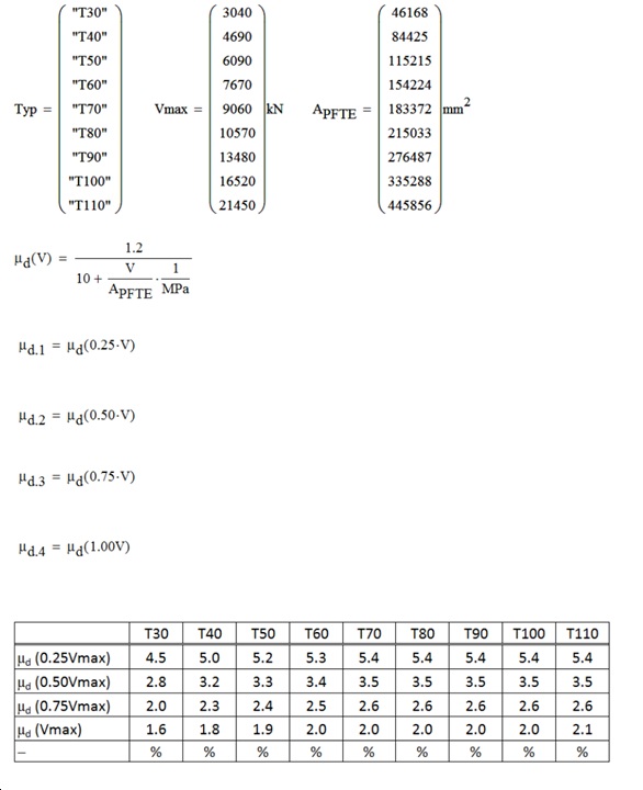
Historically, regulations specified that 20% of the total friction forces in movable bearings (maximum 10 need to be considered) or 100% in a single movable bearing should be taken into account. This load may be distributed to the fixed bearings.
16. Pedstrian dynamic laod
Defintion of dymanic pedestrian load is not defined in Eurocode 1991-2, however in some countries infomation is found in annex NA (see BS EN 1991-2:2003) but not in all.
Others only provide text as seen below (K135535).
“Load models for dynamic effects of pedestrian traffic can be sourced from established handbooks. The expected intensity of pedestrian traffic should be taken into account”.