
Future developments
…using sustainable design
The ideas presented below have the potential to reduce environmental impact through measures such as reduced material consumption, extended product lifespans, and, in the long term, more efficient and faster construction methods. While many of these concepts are not new, they may gain renewed relevance with further development.
1. MAINTENANCE
1.1 Surface drains
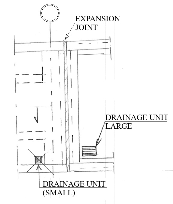
Possible methods to reduce number of surfaces drains (”ytavlopp”) .
- Introduce regulations with requirements for design runoff time, taking into account rainfall duration and the discharge capacity of the drainage system.
- Use fewer drainage with higher discharge capacity.
- Develop watertight expansion joints at end support, enabling the installation of larger drainage units in the backfill behind the abutment.
1.2 Watertight expansion joints
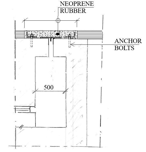
Watertight expansion joints might be achieved using neoprene rubber layer. Maintenance would be simplified.
1.3 Roof on bridges
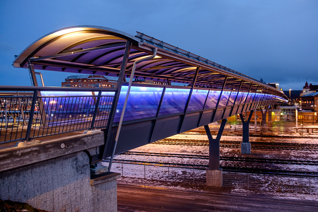
Roof on bridges may extend service life and reduce maintenance cost.
1.4 Renovation expansion joints
When replacing smaller expansion joints (movement range < 90 mm), the option of removing the joint entirely might be considered.
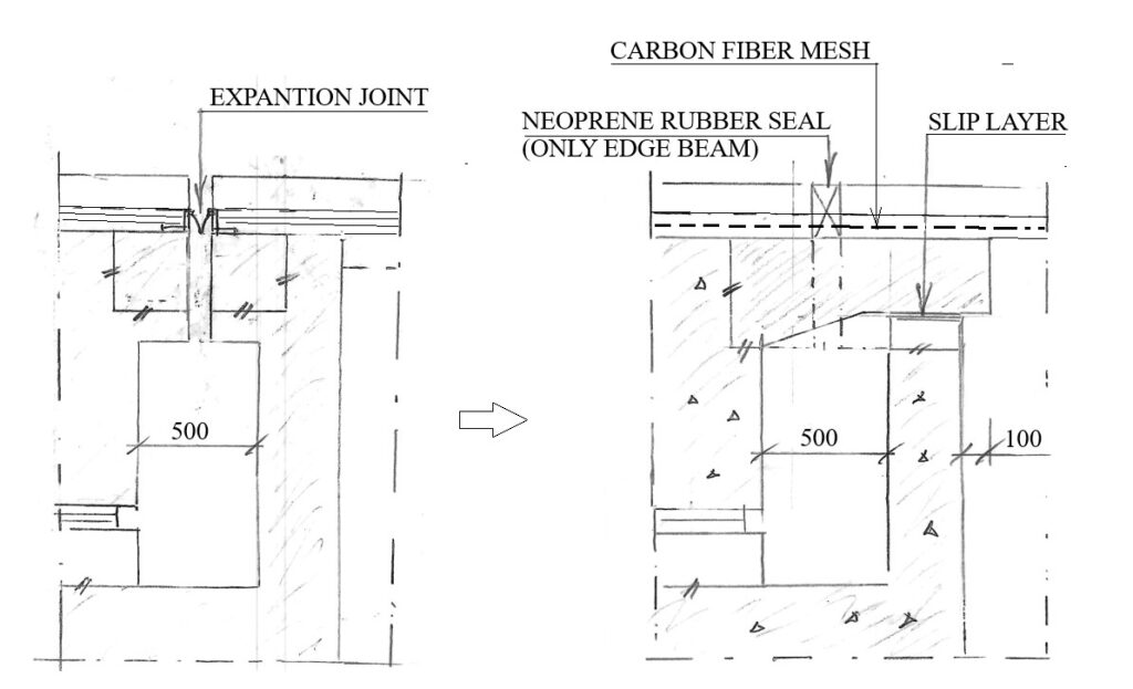
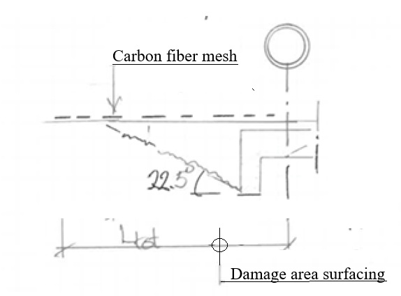
Removing the joint will expose the pavement to structural movements, which may lead to cracking and damage. The risk of damage can be reduced by reinforcing the pavement, for example with carbon fiber reinforcement.
1.5 Edge beams
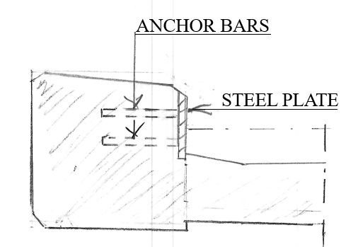
Extend the service life of edge beams in areas exposed to mechanical wear, particularly from snow removal equipment.
1.6 Long bridges without expensive expansion joints
Damage to surfacing at bridge ends caused by horizontal movement could be limited by incorporating carbon fiber mesh into surfacing. This may allow for increased bridge length for end-shield bridges, thus less need for bridges with expansion joints that are expensive to maintain.
1.7 Surround concrete structures with blasted rock
Use “SJ ballast” (100 mm) on slopes closest to retaining structures to reduce the risk of graffiti since surface unfriendly for artists to stand on.
1.8 Avoid concrete retaining walls
Replace concrete retaining structures with stone walls constructed as gabions.
1.9 Rebar cage instead of fixed bearing
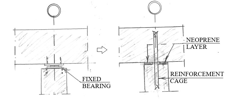
Fixed bearing might be replaced by a stainless steel reinforcement cage as seen below.
2. ENVIROMENTENTAL MATERIALS & ARCHES
2.1 Arch bridges
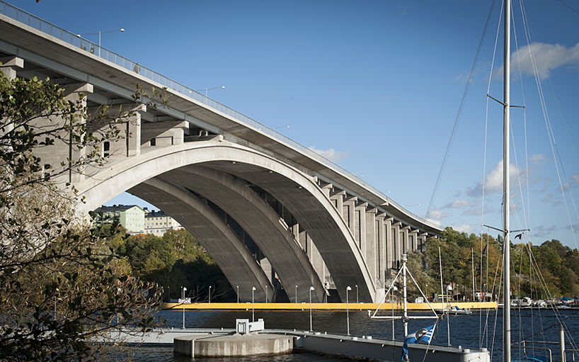
Arch bridges have been used for a very long time. Originally, they were built from stone, later, and in modern times also from concrete, steel and wood. This type of bridge is historically known for its long service life, since the main structure (arches) is primarily subjected to compression. This is advantageous because compressive stresses rarely lead to cracking. Also the mainstructure is protected by deck, which acts like a protective roof.
The use of arch bridges in materials such as steel, concrete, and stone is considered environmentally beneficial, as they require relatively small amounts of material. In addition, they are often regarded as aesthetically pleasing structures.
Arch bridges where replaced by beam bridges due to less man hours neeeded for construction. This since formwork was simpflied even though material use was often higher.
Arch bridges can be used for both long spann (200 m) and short spans (30 m). For short spans corrugated circular steel sheets might be used as formwork.
Concrete: long span
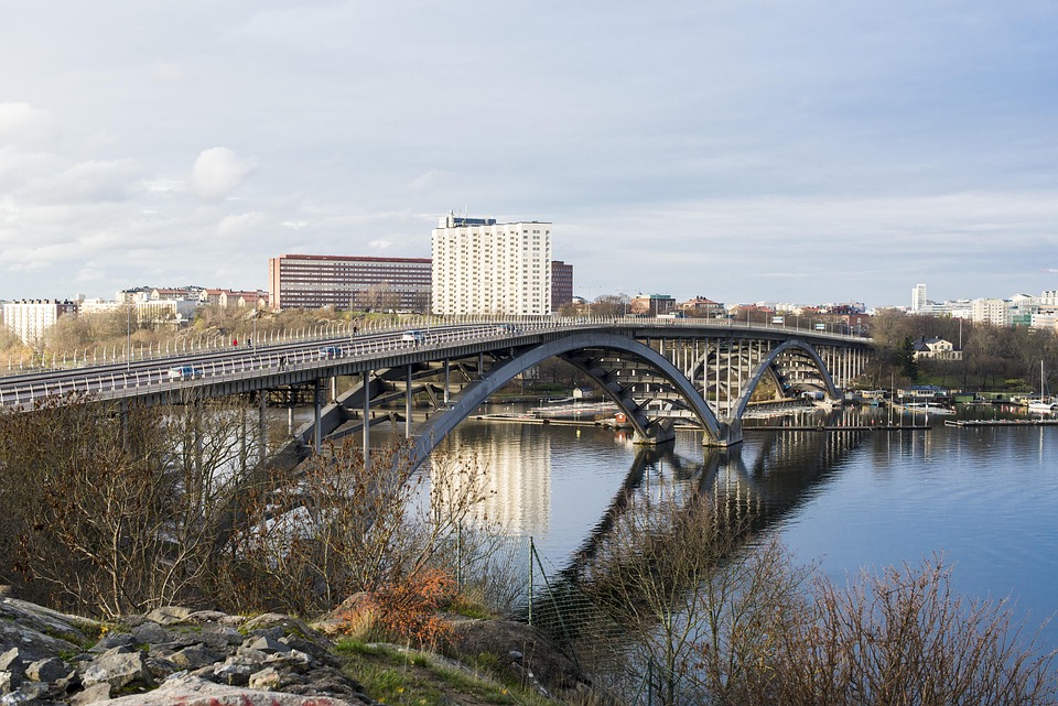
Steel: long span
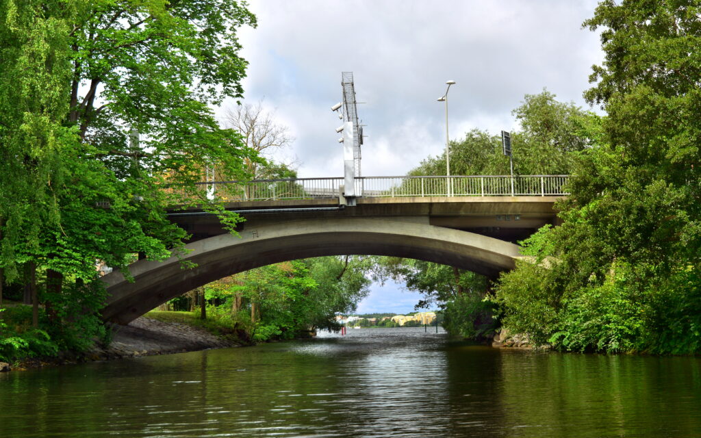
Concrete: short span
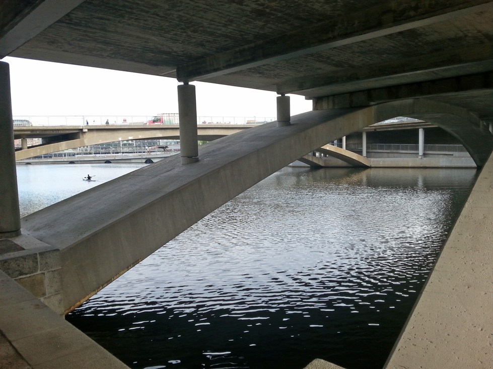
Concrete: medium span
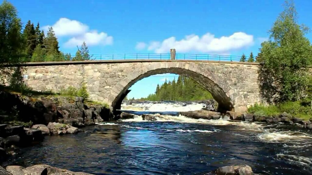
2.2 Masonary (stone) bridge
Masonry (stone) bridges are considered to have lower enviromental impact than steel and concrete, in addition to offering long service life and architectural appeal. Dominant building material until beginning of 20th century. Formwork perhaps using circular corrugated steel sheets and use Waterjet cutting of stone instead of traditional stone carving.
If you’re interested in the design of stone bridges, you may want to download the file below.
2.3 Pedestrian passages
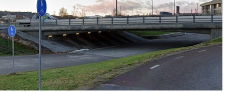
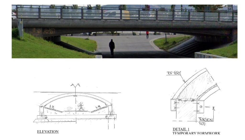
Many pedestrian passages under major roads are perceived as unsafe, dark, and uninviting. This is especially the case when they are designed as narrow tunnels, where limited visibility and uncertainty about what awaits at the tunnel exit, leads to a feeling of insecurity. The design shown below is considered successful, as it addresses these issues.
2.4 Fauna bridge
Fauna bridges are intended to help animals safely cross existing roads. Slopes should not exceed 15% .
A bridge that is wider at the ends and narrower in the middle can be advantageous. Animals perceive the crossing as more open and safer, while material usage may be reduced.
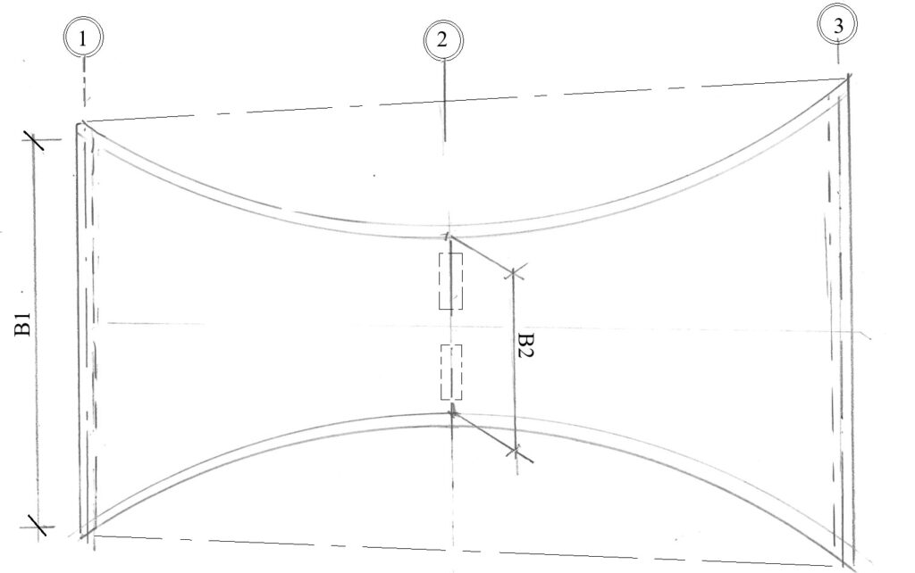
PLAN
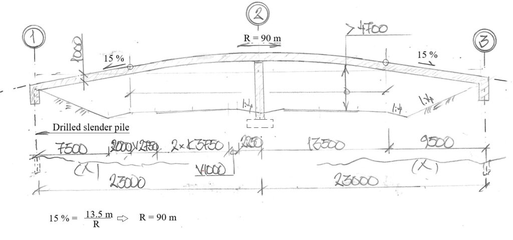
ELEVATION
2.5 Green concrete
Green concrete is a type of concrete that is made with “sustainable” materials. Generally “fly ash” comes from fosile furnaces. In order to produce green concrete “fly ash” is needed, thus risk demand for green concrete creates a demand for “fly ash”.
Another problem with green concrete is that at present it requires lower vctekv than without “fly ash”, thus increasing demand for “fly ash” even further.
Green concrete is a short term solution of how to make best use of existing use of fosile material in furnaces, thus not a longterm sustainable solution.
A more effective approach is to optimize concrete utilization through advanced analytical design method using transparent design.
3. PRODUCTION
3.1 Void tubes in bridge decks
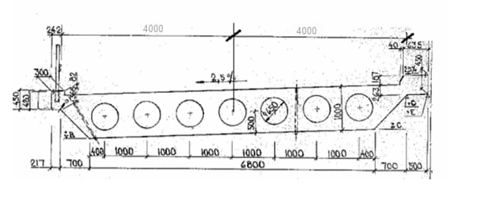
Improve methods for weight reducing void tubes in bridge decks by optimizing anchorage during manufacturing and developing shapes and materials.
3.2 Steel bridges without using paint
Steel bridges constructed with structural steel of high corrosion resistance (SSAB Weathering or equivalent) do not require coating (painting).
3.3 Steel bridges without welding
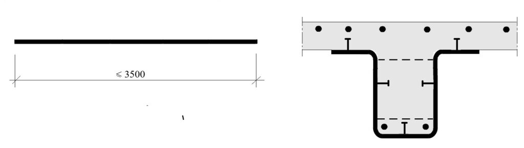
Manufacturing of steel sections from high strength steel sheets through folding (bending) to mimimize need for welding, reduce construction height and add architectural appeal. The idea is to use high strength steel (“WELDOX” or equivalent) in a composite steel girder.
3.4 Using expensive tie rods for both construction and operational stage
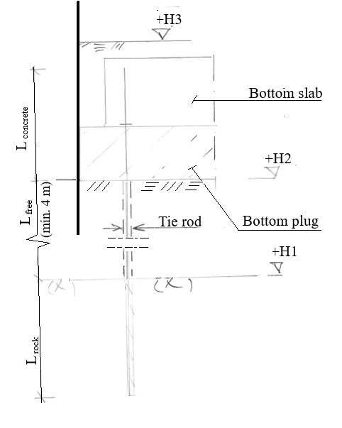
During the construction of bridge supports in water within “rectangular sheet pile cofferdams”, vertical tie rods used to anchor concrete bottom plug should also be utilized in operational phase to resist ice forces and accidental impact loads against abutment. Important that vertical ties have low stiffness and double corrosion protection.
3.5 Expensive to construct sheet pile cofferdams when foundation is deep
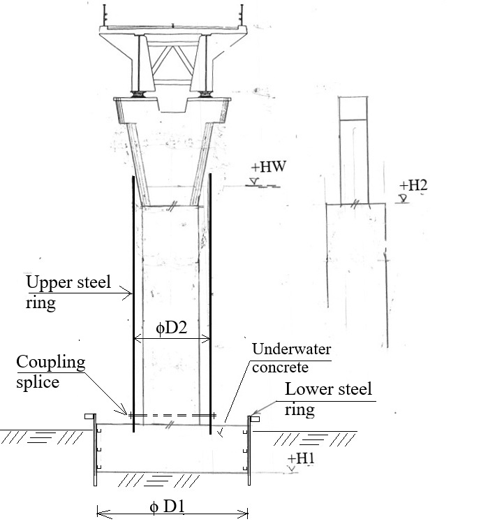
It is expensive to construct “rectangular sheet pile cofferdams” (bottom plug & tie rods) when depth to sea bottom is high.
A possible way to solve this is constructing a circular form for bottom slab. Then applying a circular form for the construction of column, see sketch below.
3.6 Avoid visible retaining structures
If the bridge is extended, the need for adjoining retaining structures at the bridge ends is reduced. Fully concealing the abutments inside embankment has several advantages. Avoids risk of graffitti, reduces need for railings and aesthetically pleasing.
3.7 Protecting design timber
Use structural timber with “double wood protection based on linseed oil” (applied under vacuum), instead of using conventional “hazardous pressure treatment”.
3.8 Prefabricated design
In urban environments or in close proximity to heavily trafficked railway lines, minimizing construction time is critical reducing risks and disruptions to traffic and surrounding activities.
Steel beams are commonly used as permanent load bearing formwork for superstructures. However, this approach is not widely applied to concrete beams. It is also rarely used for substructures such as piers and abutments. These are typically constructed in situ, although this method is common in some countries, as shown in the suggestions below.
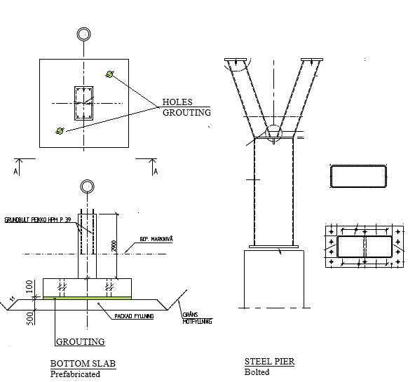
Intermediate support
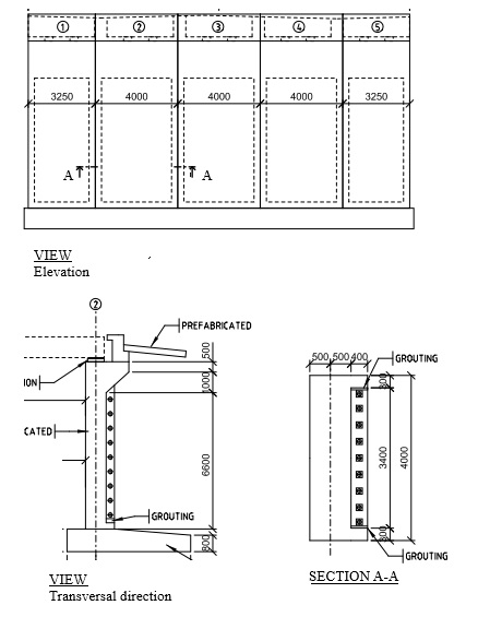
End support
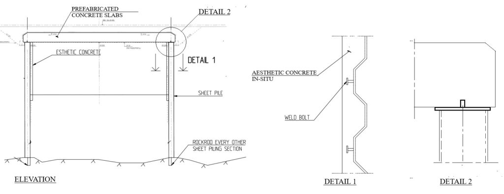
Sheet pile bridge
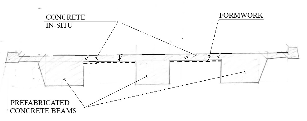
Prefabricated concrete superstructure
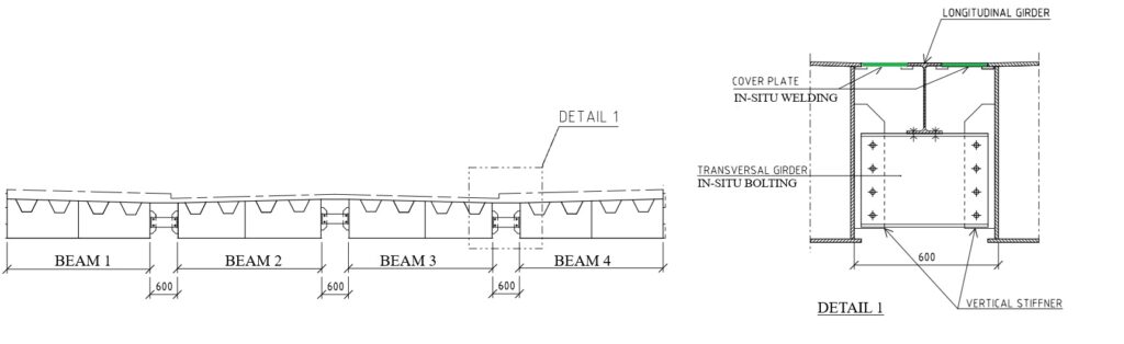
Prefabricated steel superstructure
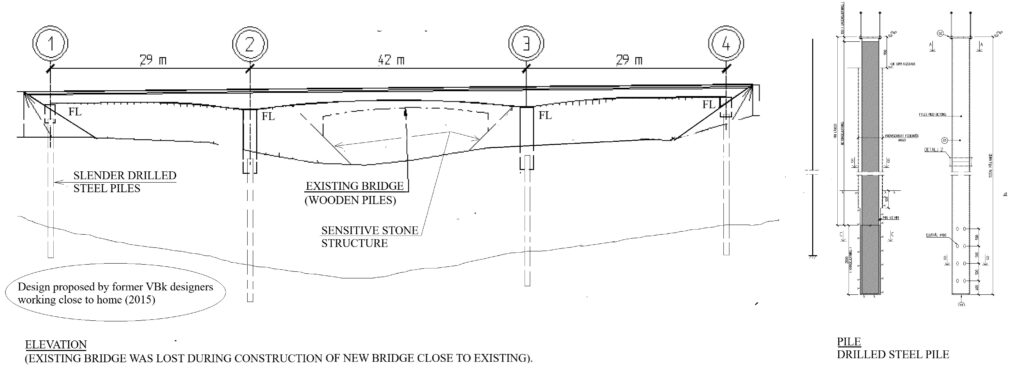
Drilled slender piles (RD) without using bottom slabs.
4. DESIGN SIMPLIFICATIONS
4.1 Pedestrian dynamic loads
The general overall document Eurocode 1991-2 does not contain definition of dynamic pedestrian loads, however some have national annex NA have needed information, see example BS EN 1991-2:2003. Would be useful to incorporate pedestrian dynamic load into 1992-2 (or every NA).
4.2 Load coefficient table (single) for road bridges
Previous regulations provided a derived load coefficient table, that could be used to perform both geotechnical design (GEO) and bridge structures (STR).
In this proposal, geotechnical loads (earth pressure & surcharge) according to material model M1 is assumed. Also safety class SK 2 has been assumed to GEO and SK 3 to STR.
Below, a proposal is presented for a simplified load coefficent table applicable for both geotechnicial and structural design.
The influence of varying friction angles in the backfill has been evaluated. Verification has been performed for both gravel and blasted rock .
Please observe all tables are only feasibility studies for future development, thus none of tables have been accepted by any regulatory authority in any country.
Table for ultimate state (ULS)
Permanent loads:
| Nr | Load | ULS:B | ULS | |
|---|---|---|---|---|
| 1 | Dead weight | max | 1.35 | 1.20 |
| min | 1.00 | 1.00 | ||
| 2 | Surfacing | max | 1.50 | 1.35 |
| min | 0.90 | 0.90 |
||
| 3 | Overburden filling | max | 1.50 | 1.35 |
| min | 0.90 | 0.90 | ||
| 4 | Earth pressure | max | 1.50 | 1.35 |
| min | 0.90 | 0.90 | ||
| 5 | Water pressure | max | 1.35 | 1.10 |
| min | 1.00 | 1.00 | ||
| 6 | Support settlement | max | 1.35 | 1.20 |
| min | 0 | 0 | ||
| 7 | Shrinkage | max | 1.35 | 1.20 |
| min | 0 | 0 | ||
| 8 | Prestress | max | 1.35 | 1.35 |
| min | 1.00 | 1.00 |
“ULS” is for normal operations, while “ULS:B” for construction stage.
Variabel loads (the highest value given in column ULS is only to be applied to one load simultaneously):
| Nr | Load | ULS:B | ULS |
|---|---|---|---|
| Load modell LM 1: | |||
| 9 | Boggie load (TS) | 1.15 | 1.05 / 1.50 |
| 10 | Surface load (UDL) | 0.60 | 0.60 / 1.50 |
| 11 | Brake load | 0.85 | 0.85 / 1.15 |
| 12 | Lateral load | 0.85 | 0.85 / 1.15 |
| 13 | Centrifugal load | 0.85 | 0.85 / 1.15 |
| Load modell LM 2: | |||
| 14 | Single axle | 0 | 1.05 / 1.50 |
| Complementary loads: | |||
| 15 | EG A & B | 1.15 | 1.15 / 1.50 |
| 16 | Brake load | 0.85 | 0.85 / 1.15 |
| 17 | Lateral load | 0.85 | 0.85 / 1.15 |
| 18 | Centrifugal load | 0.85 | 0.85 / 1.15 |
| 19 | Temperature | 0.90 | 0.90 / 1.50 |
| 20 | Wind load | 0.45 | 0.45 / 1.50 |
| 21 | Surcharge | 1.15 | 1.15 / 1.60 |